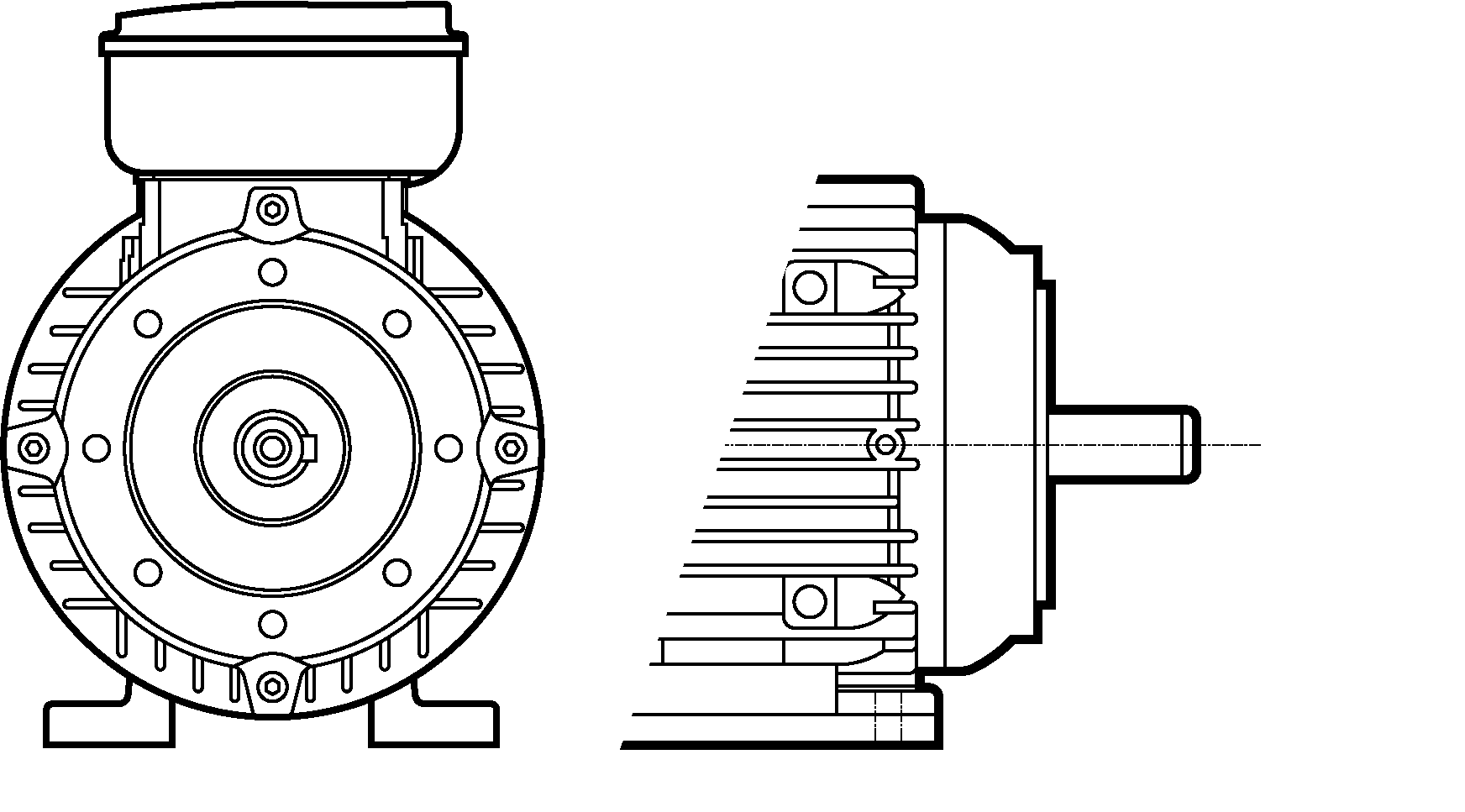
The different mounting options for electric motors.
An electric motor’s mounting depends on its application, with various options available to suit specific requirements. These options are detailed below.
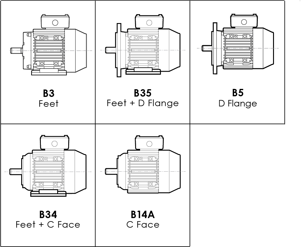
B35 Feet and D Flange / B5 D Flange (no feet)
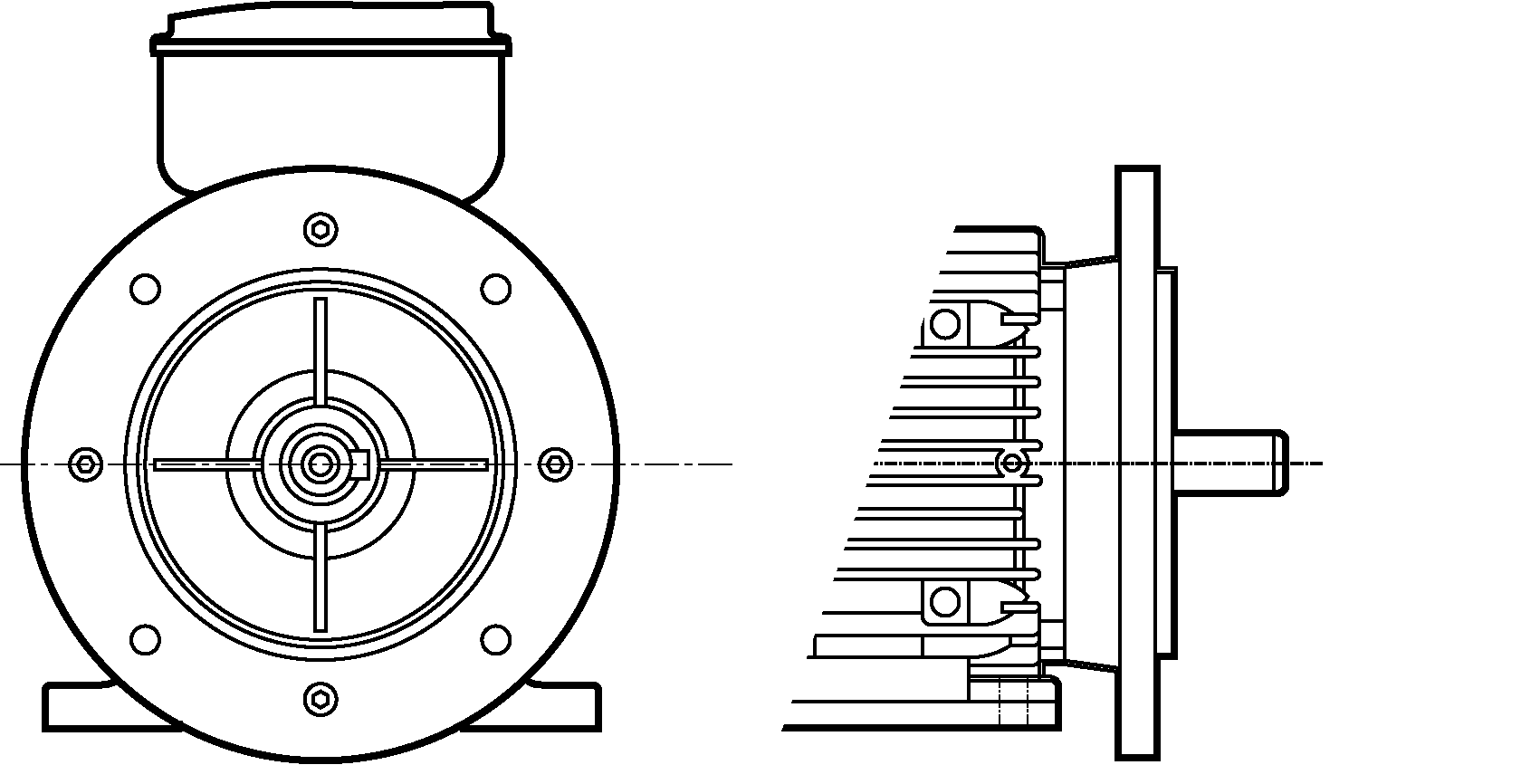
B34 Feet and C Face / B14A C Face (no feet)
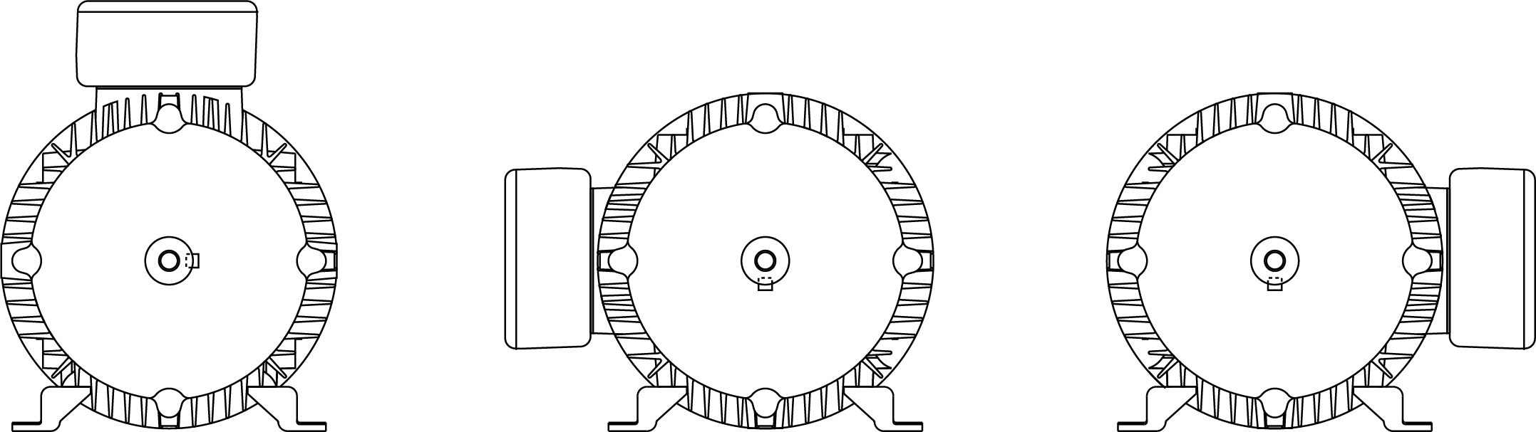
B3
- This motor has feet
- Foot mounted, end shield on drive (shaft) end
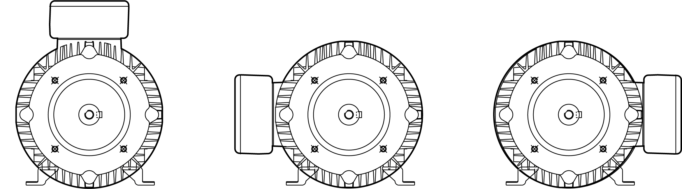
B5
- D flange, no feet
- Also known as an A flange
- The outer diameter is larger than the motor body.
- The motor is attached to the driven equipment by bolts and nuts or studs protruding from the driven equipment.
B35
- D flange and feet
- The outer diameter is larger than the motor body.
- The motor is attached to the driven equipment by bolts and nuts or studs protruding from the driven equipment.
- The motor has feet
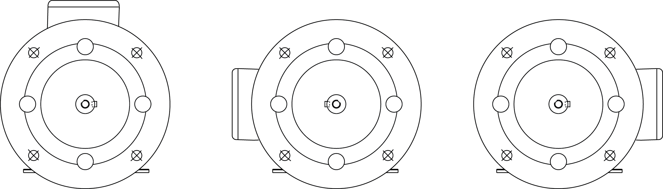
B14
- C face, no feet
- The face is smaller than the motor body and has threaded holes.
- The driven equipment is attached by bolts.
- The motor bolts to the face not through a flange.
B34
- C face and feetThe face is smaller than the motor body and has threaded holes.
- The driven equipment is attached by bolts.
- The motor bolts to the face not through a flange.
- The motor has feet
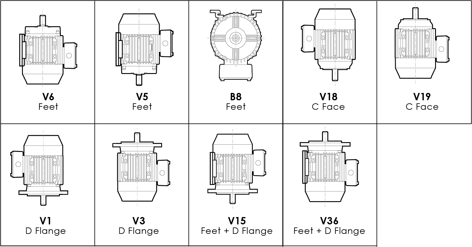
Terminal box positions on three phase motors are either fixed to the top (standard) or positioned to the left or right through movable motor feet. ABB three phase motors have the terminal box fixed to the top when viewing from the drive end shaft. Brook Crompton motors removable feet allow the terminal box to be positioned to the top, right or left. Below are the standard and vertical mounting options with the standard top terminal box position. Terminal box and mounting information is required when specifying your motor requirements.
STANDARD ELECTRIC MOTOR MOUNTINGS
VERTICAL ELECTRIC MOTOR MOUNTINGS (Requires application relevant components)
For more information on ABB motors click here. For Brook Cromption motors click here and their multi mount options click here.